If you've read my previous post you'll know that, while I'm pretty happy with our choice of an air to air minisplit heat pump as our only heat source, it had some disadvantages compared to a more conventional (for the UK at least) air to water system with radiators/underfloor heating. You'll also know that I thought some of these might be solvable. Specifically the unit short-cycled a lot at low loads and was imprecise at hitting the desired indoor temperature.
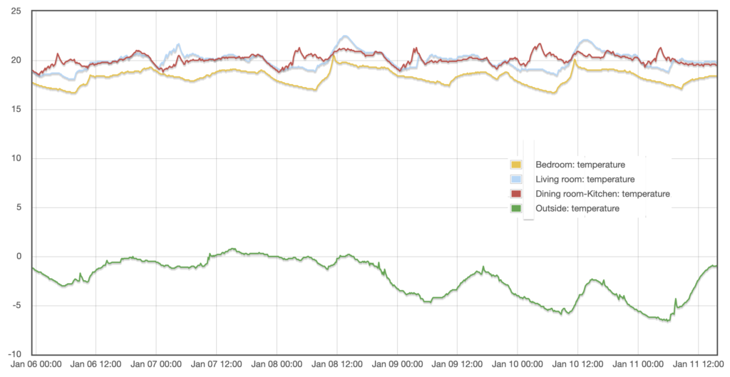
Until now, the heat pump relied on a thermister built directly into the indoor unit. This meant the system was trying to measure the room air temperature right above the warm air outlet, leading to inaccuracies. These were especially bad during cold weather when the unit was working harder, and it wasn't unusual to have to push the setpoint to 23 or 24 °C in order to achieve 20 °C in the room. I suspected the thermister location was also part of the reason the unit cycled so much at low loads.
Because of these two problems I wouldn’t have felt completely comfortable, as a consultant, recommending this setup to a 'normal' person. As a geek, I can just about tolerate manually adjusting the setpoint depending on the outdoor temperature and occasionally switching the heating off completely when I notice it cycling, all in the name of research. But I suspect most people would either get very annoyed at this or simply decide the heating didn't work very well.
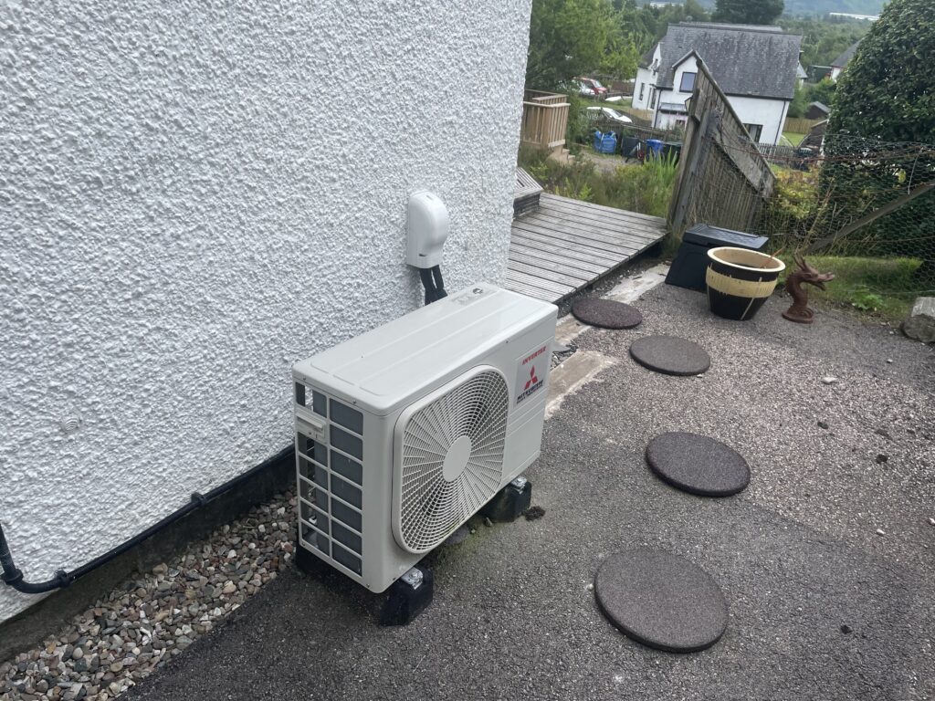
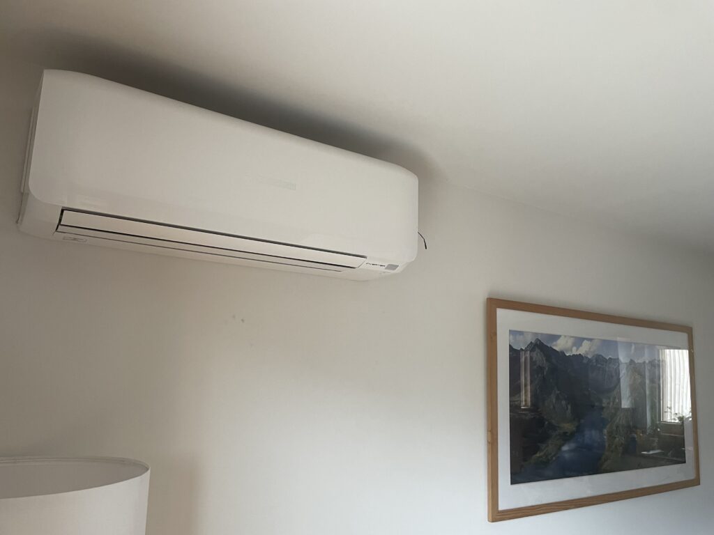
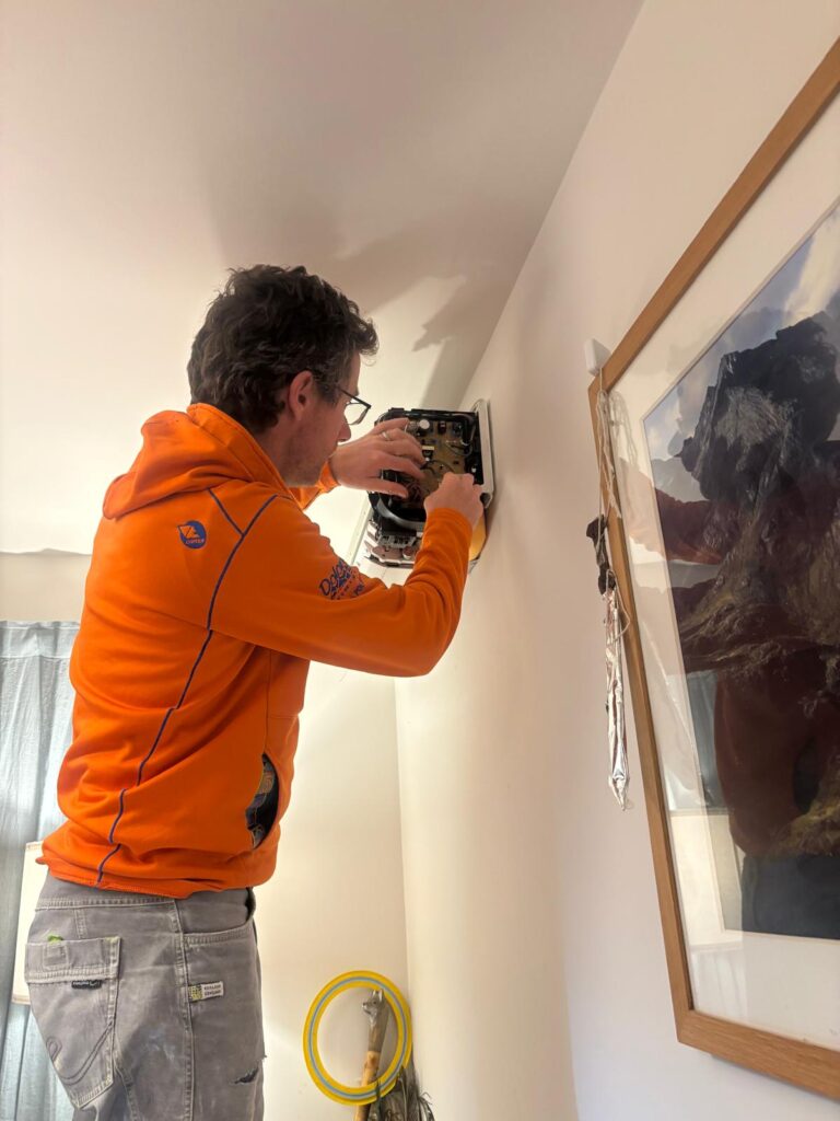
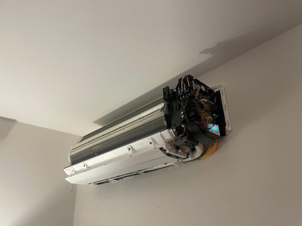
To try and solve this, I've recently installed a remote thermostat.
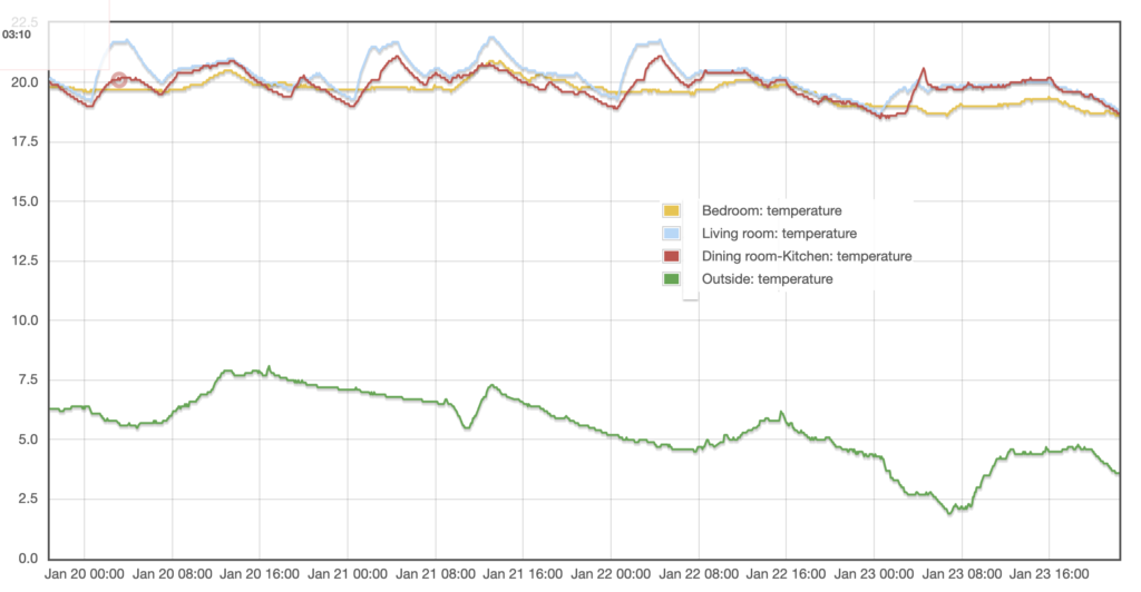
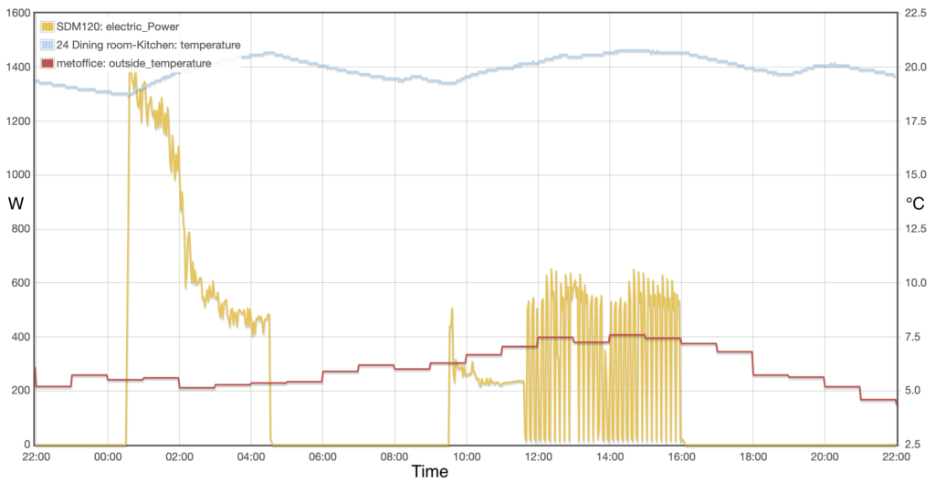
We've only had this up and running for ten days or so, but the results so far are very promising:
- It’s far better at holding a steady setpoint.
- Cycling is much reduced. At low loads it will do longer cycles than previously, and often switch off for long periods at a time, if the room is at the setpoint temperature, when previously it would have cycled every five minutes or so.
It’s still early days, but if it keeps performing how it has in the last ten days this now feels like a configuration I could recommend to someone who just wants their heating to work without fussing over it.
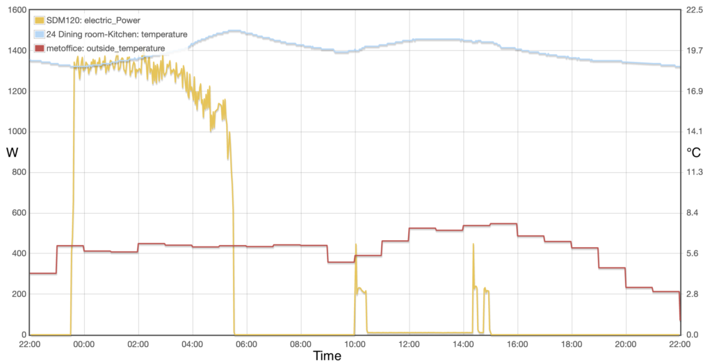
Interestingly, it looks like it might be better at 'overheating' the room it's in during cheap electricity periods - the system often wasn’t achieving the target temperature before. Now it achieves this more reliably, which means we should be able to shift more of our heating electricity demand to the off-peak period of between 2330 and 0530. Over the past five days, which have been cold (around freezing), 70% of our heating electricity use has been in off peak hours. That's a lot more than the average for last year (56%), and a even better than the same 5 days in 2024 (which were also quite cold), where only 44% of heating electricity use was off peak. There's quite a lot going on there that confuses the picture - different weather, different hot water demand, longer off peak period due to a change in tariff, but as an early result it's promising. I'll have to wait till this time next year to see if it makes much of a difference over a longer period.
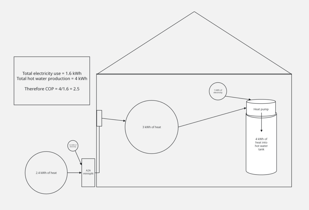
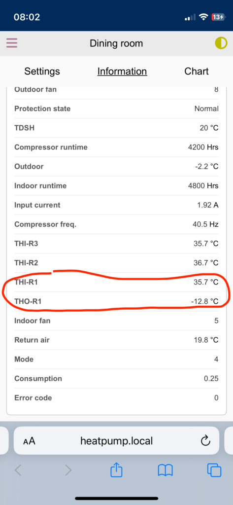
The new kit also comes with a web interface, which allows me to see some refrigerant temperatures from the unit in operation. This opens up the possibility to get a better estimate of the coefficient of performance (COP) under different conditions. I'm not sure exactly where in the heat pump cycle these temperatures are taken, but based on chatting to John Ewbank, who's doing an interesting study on air to air heat pumps, I've plugged what I think are the right numbers into the Carnot formula for the maximum theoretical COP. I'm also not sure how much to reduce these numbers by in order to get realistic real world COPs (half?)*, but, assuming I'm using the right measurement points it confirms something I'd suspected:
- The best COPs are when the unit is operating at its lowest power input. At input powers just above 200 W the Carnot efficiency is just above 8.
- When it's working harder the COP is not as good, with a Carnot efficiency of just between 6 and 7 for input around 500 W and a Carnot efficiency of just above 5 for an input power of 1300 W
These figures will change with the outdoor air temperature, but they emphasise that, all else being equal the unit should be run for long run periods. Of course, because we're on a variable tariff all else is not equal, and I suspect our tactic of overheating the dining room slightly at night is worth it - the electricity is more than 3 times cheaper then, and I don't think the reduction in COP, or the slight increase in heat loss due to warmer indoor temperatures overnight, will be anywhere near enough to offset that.
So overall very good. There are two things that I'd like to be able to do but still can't:
- Have more programmable schedules. At the moment the unit is set to heat to 22 °C during the off-peak period and 20 °C during the on-peak. Some more flexibility would be helpful here.
- Remote control from outside the house. I can now control the unit from my phone, but only when I'm on the same WIFI network. Being able to turn the unit on or off from outside the house would be really useful - for example to warm the house back up after a holiday, which can take several days because the power is low.
- I'd like to get an automatic log of the refrigerant temperatures so I can look in more detail at what COPs I'm getting and look in more detail at whether it's worth running the unit 'hard' during off-peak periods.
I've a couple of ideas of how I might do those things. Watch this space.
* If anyone has any knowledge about which temperatures I should be taking from a Mitsubishi Heavy Industries unit to plug into the Carnot formula, or how much to reduce the Carnot COP by in order to get to a real-world COP estimate for an air to air minisplit, please leave a comment below.